RF SIGNAL CONDITIONING
(FULLY INTEGRATED SYSTEMS)
complete active gain control & interference mitigation for optimum receiver range
PRODUCT OVERVIEW

[insert new diagram]

[insert new diagram]
about
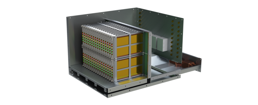
ARS Products’ Radio Frequency Signal Conditioners (RFC), or fully integrated systems (Model 810), are designed to be comprehensive and fully autonomous in changing environments to suppress down stream tuners and keep receivers within their optimum operating range. Model 810 automatically adjusts the gain to deliver optimum Noise Figure (NF) and Intermodulation Distortion (IMD).
ARS’s front-end “Radio Frequency Signal Conditioning" devices utilize a suite of mitigation resources, including signal analyzers or sub-band interferer detection & controller modules, to keep all incoming signals below the user-identified threshold.
The suite of mitigation resources include:
-
Non-Reflective Limiters * (NRL) [Fast Transients]
-
Cancelers [Coherent and/or Reference-less]
-
Fixed Filters [Band Stop & Band Pass]
-
Programmable Attenuation
-
Gain Stages ** [Amplification]
* When in limiting, conventional diode limiters distort the incoming signal and reflect the energy back to the antenna. NRL does not distort or reflect (re-radiate).
** ARS offers many push-pull options for higher IMD^2 performance.
The signal analyzer included in our conditioning systems continuously scans the incoming spectrum and picks the appropriate resources to suppress down stream tuners and keep receivers within their optimum range.
theory
The RF Conditioners are best suited for agile/dynamic environments due to the autonomous mitigation architecture (flexibility of selected components and overall circuitry design) which provides an expedited response to continuous or persistent variable frequency/power conditions.
In the RF Conditioner block diagram outlining the circuitry of a single channel and single sub-band, there are three distinct modules that comprise the “front-end”: “Input Detection & Mitigation Routing Section”, "Selective Mitigation Modules", “Gain & Protection”, and “Sub-band Spectrum Analyzer & Controller”. While each module is in communication with one another rather fluidly, as illustrated in the diagram via purple lines, for the purposes of discerning information, let’s consider each “module” a “phase”. For example, when the signal feeds through the ‘input’, the signal is coupled at the start of “phase 1”: the “Input Detection & Mitigation” module. The coupled or copied signal is then sent to phase 2, the “Sub-band Spectrum Analyzer & Controller” module, while the original signal passes through a high-power attenuator.
Although front-end attenuation is not the most desirable technique, as mentioned in the theory section of “Interference Mitigation”, the high-power attenuator included in phase 1 serves two purposes. The first, to effectively control the incoming signal level to dissipate or absorb any unwanted power. The second, to provide a level of protection for the hardware the follows. Overall, the loss incurred by front-end attenuation is truly minimal compared to replacing a module or entire system due to front-end overload.

Single Channel Architecture
APPLICATION
ARS Products’ Radio Frequency Signal Conditioners (RFC), or fully integrated systems (Model 810), is a module system. It can be configured for a single channel; or for multiple channels. In multiple channel configurations the 810 can be set up in tracking mode, preserving Direction Finding (DF) capabilities.
The 810 can be configured in sub-bands, to further optimize NF and IMD. Each sub-band has separate independent thresholds. Sub-bands multiplexers can be directly integrated into the 810.
Each band (or sub-band) has a dedicated signal analyzer. The signal analyzer continuously scans the incoming spectrum and picks the appropriate resources to keep the down stream tuners and receivers in their optimum operating range.
Our specialized backplane and control topologies yield better isolation and spurious performance than conventional techniques.
Unique specific power supplies further reduce consumption and heat dissipation.
IMPLEMENTATION
The Model 810 is also software customizable. The user can specify exclusion bands and frequencies. The user only needs to specify the RF threshold level and the 810 will keep all incoming signals below that threshold. The 810 automatically adjusts the gain to deliver optimum Noise Figure (NF) and Intermodulation Distortion (IMD).
In the example below, the 810 is adding gain to Sub-band A, Sub-band B has unity gain and a notch inserted, sub-band C has attenuation and a and-stop filter engaged, and Sub-band D has attenuation.

810 sub-band Performance Data
DEVICE SPECIFICATIONS
Our 810 units are meticulously designed to meet exact customer specifications and incorporate our full suite of Interference Mitigation solutions. To ensure clarity and ease of selection, we have provided the data sheets for each product series (FPNF, NRL, Canceler, etc.) within the entire system, detailing all available options.

Non-Reflective Limiters-
Device Specs Table

FP Notch Filters -
Device Specs Table

.png)


