
.png)
"Inventing For Tomorrow"

SIGNAL CANCELERS
FREQUENCY SELECTIVE INTERFERENCE Suppression


PRODUCT OVERVIEW

TX DIRECT REFERENCE
ABOUT
ARS Products’ Cancelers are designed to prevent receiver overload or desensitization by reducing transmit levels before entering the input of co-located receivers.
ARS’s “Selective Radio Frequency Interference Reduction” devices utilize techniques centered around the ability to selectively attenuate strong signals while simultaneously leaving weaker signals unaffected.
There several variations of canceling devices that cater to different, unique environments, and there is not one standard device that fits all possible applications of use.
The two classes of equipment used for “Selective Radio Frequency Interference Reduction” are the Frequency Programmable Notch Filters (FPNF) and Signal Cancelers.
Signal Cancelers are further divided into Coherent and Reference-less based on the circumstantial parameters and end-goal/needs-based function.
mODEL 730
FREQUENCY PROGRAMMABLE
NOTCH FILTER

mODEL 720

COHERENT
CANCELER
model 718

REFERENCE-LESS CANCELER
COHERENT CANCELERS
theorY
The Coherent Cancelers are best suited for co-located interferers due to the Coherent’s need for a direct sample (i.e. TX Reference) of the interferer’s input frequency signal to generate a more precise and effective cancellation method.
The block diagram maps both the direct sample and radiated signal’s expected route during routine use.
Within the diagram, the interferer’s input frequency is copied into two signals via coupler installed along the transmitter (TX) feed up to the TX Antenna.
One of the now two signals becomes the direct sample (i.e. TX Reference), which is then fed to the Coherent’s Canceler Module along the RX Input feed.
Whereas the second signal moves up through the coupler and radiates from the TX Antenna to the RX Antenna then down the RX Input feed.

TX DIRECT REFERENCE

INSIDE CANCELER MODULE
Inside the Canceler Module, the direct sample (TX Reference) is manipulated via a Vector Modulator (VM) into an out phase (180 degrees) version of the aforementioned copied radiated signal.
The manipulated signal (former TX Reference or direct sample) is then combined (or rejoined) with the radiated signal via a summer, thus completing the vector cancellation process.
ADDITIONAL CONSIDERATIONS
-
Zero amplification of input frequency in the TX Reference path, hence no added noise.
-
Since the Coherent Canceler uses a direct sample (TX Reference) against itself, it is the only signal that will be canceled.
-
Adjacent Signals of Interest (SOI) will not be impacted at all (up to 1KHz in frequency away from the TX signal).
-
Coherent Cancelers yields narrowest bandwidth possible however, it is limited by the need for a direct sample (TX Reference).
-
Coherent Cancelers can be cascaded with appropriate control to form dual loop designs. ARS has manufactured dual loop coherent cancelers that deliver 90+ dB of canceling.
-
COHERENT CANCELER LIMITATIONS: Required to have direct sample (TX Reference)

[INSERT NEW DATA IMAGE]
APPLICATION
ARS Products’ Model 720 V-UHF Canceler's function is to prevent receiver overload or desensitization by reducing (canceling) transmit signal levels before entering the input of co-located receivers.
-
Model 720 is a fully integrated canceler that can accommodate up to two co-located transmitters.
-
The unit is located between the receive antenna and the receiver.
-
A user provided coupler (20 dB typ.) is installed between the transmitters and the transmit antenna(s) to provide TX sample(s) to the canceler.
Model 720 is ARS Products' third generation of coherent cancelers and builds upon our historical iterations by adding a second source capability and wide band operation (30-470 MHz)
REFERENCE-LESS CANCELERS
INDIRECT REFERENCE
THEORY
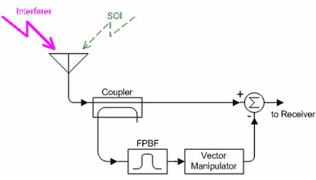
Reference-less Cancelers are best suited for when there is no reference or direct sample available for manipulation, therefore the reference is determined in parallel through a separate spectrum analyzer, coupled, then generated indirectly via Frequency Programmable Band Pass Filter (FPBF).
Within the diagram, the entire interferer’s signal is coupled and separated into two signals.
One of the two copied signals is then passed through the Frequency Programmable Band Pass Filter (FPBF) programmed using the information collected via spectrum analyzer before it is manipulated by the Vector Modulator (VM) to become the image signal or indirect sample.
The image signal then rejoins the second signal in the summer.
LIMITATIONS
-
The tunable Band Pass Filters (FPBF) have finite band widths, therefore as Signals of Interest (SOI's) approach the radiated interfering frequency, the SOI’s will be canceled as well.
-
The Reference-less’s cancellation of approaching Signals of Interest is referred to as “capture bandwidth”.
-
There is an amplification that occurs in the Reference-less design which is the source of the added noise.
-
In most ARS Reference-less Cancelers, the added noise is typically a hump-shape above the nose floor with a width of 15% of interfering frequency. The typical peak added noise level ranges between 6 and 15 dB depending on frequency.
-
It is important to note that most potential users of Reference-less Cancelers are not aware the added noise parameters. If these parameters are not taken properly into consideration, they may render the canceler useless. We have seen other manufacturers produce Reference-less Cancelers where the added noise exceeded 50 dB!
APPLICATION
ARS Products’ Model 718 V-UHF Canceller's function is to prevent receiver overload or desensitization by reducing (canceling) interfering signals before reaching receiver inputs.
-
Model 718 is a fully integrated canceler that can cancel up to eight interferers.
-
The unit is located between the receive antenna and the receiver.
-
The unit contains an internal spectrum analyzer for fully autonomous operation.
-
The user can specify signal thresholds and exclusion frequencies.
-
Front panel displays show the canceler status and operating conditions.
NOTE:
-
There are two canceling channels in the 30 - 90 MHz sub-band
-
Two canceling channels in the 90 - 220 MHz sub-band
-
Two canceling channels in the 220 - 380 MHz sub band
-
Two canceling channels in the 380 - 470 MHz sub band


